
Alignment and Snapping Tools
Pivot Alignment Tool
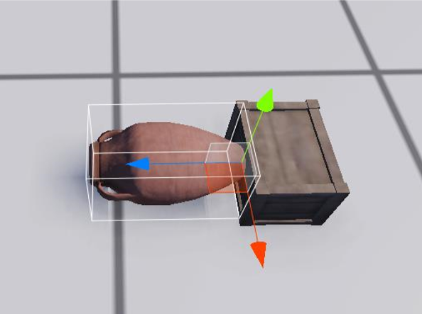
The Pivot alignment tool applies the chosen transform values of one entity to another entity. The tool makes it easier for users to create overlapping or precisely aligned entities. If an entitity is selected in the editor, the user can set up the alignment tool by pressing Alt + A. This will register the currently selected entity as the input entity. Selecting a second entity with the left mouse button, will then open the interface screen of the alignment tool.
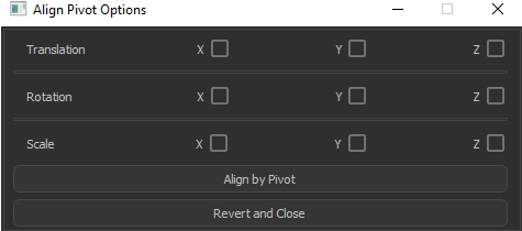
- Translation checkboxes will translate first entity on the given axis/axes.
- Rotation checkboxes will rotate the first entity without breaking the local scale. Up, side and forward vectors will be aligned depending on the checkboxes.
- If the scale checkboxes are checked, first entity’s scale component of the selected axis or axes will be set as second entity’s scale value which is shown at the inspector.
- If checkboxes are unchecked, first entity will be transformed to its initial frame.
- Align by Pivot button will apply the alignment depending on the active checkboxes and close the interface.
- Revert and Close button will transform the entity to its initial frame and revert any transform operation applied to pivot.
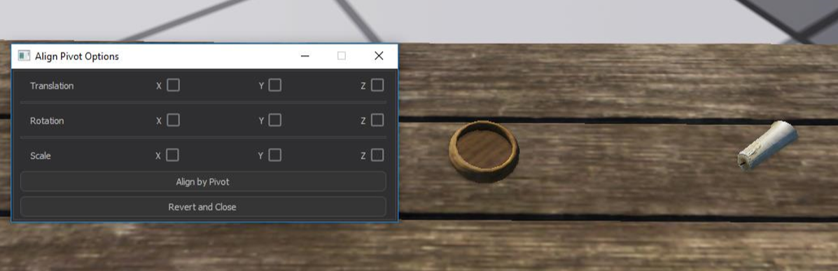
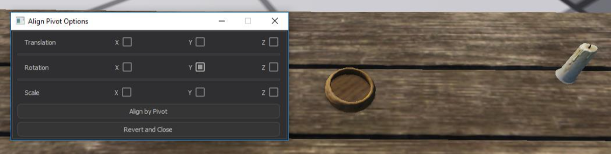
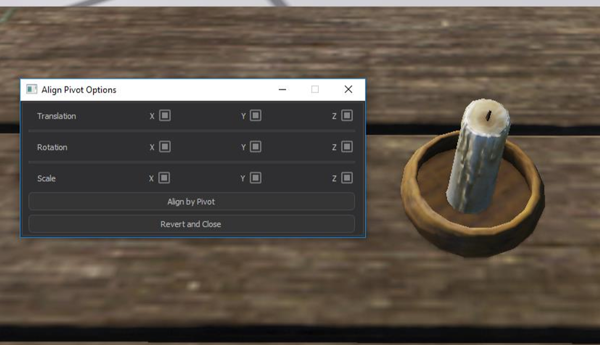
Example Usage
Surface Snapping Feature
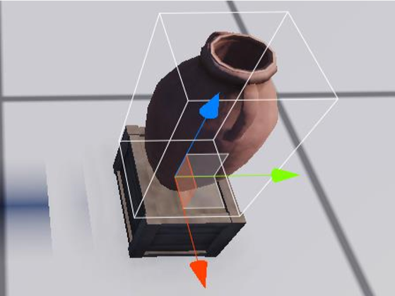
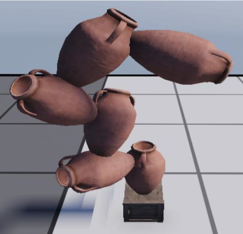
The Surface Snapping Feature allows a user to snap an entity’s pivot to the surface of another entity. Holding down the I hot-key continuously snaps the pivot of the currently selected entity to a surface that the mouse cursor intersects with. Control + Z reverts the transformation. This feature aligns the entity’s local y vector with the intersection point’s normal map, so it won’t require the user to make additional adjustments to align the entity with the surface.
Beware that this will lead to clipping, if the pivot of the entity that you seek to snap to a surface is not located on its own surface.
Example Usage
Vertex Snapping Feature
The Vertex snapping feature allows users to choose any vertex from a selected entity and place that vertex in the same position as any vertex from another entity of their choosing.
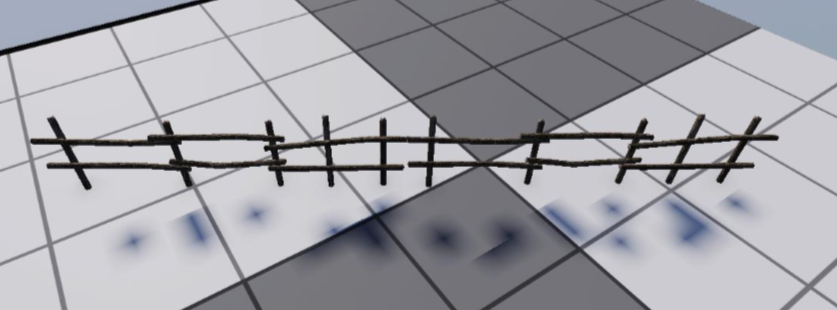
Alt + V activates and deactivates the vertex snapping feature. It only becomes active if an entity has been selected in the editor. There is a button on the editor toolbar as well, which acts like the hot-key.
After activating the tool and while the left mouse button is in a “down” state, the chosen entity’s selected vertex will continuously snap to the vertex of another, highlighted entity that is closest to the mouse ray’s intersection point. If the distance between the intersection point and the closest vertex is bigger than 2.0f or there is no second entity highlighted, nothing will happen.
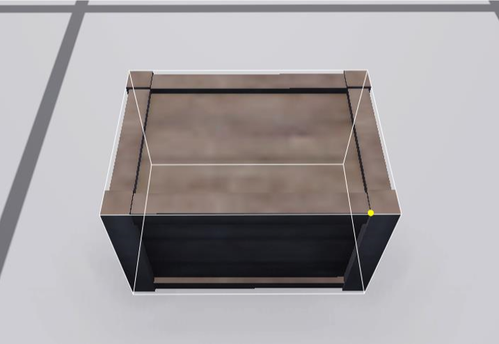
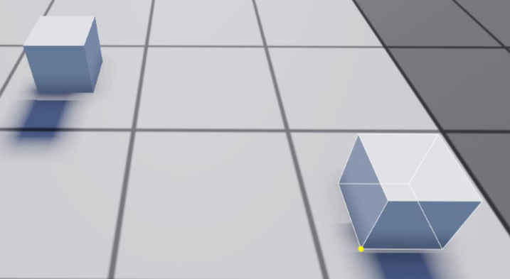
Also, a yellow sphere will be rendered on the vertex to provide head-up display. Thus, user can choose any vertex by moving the mouse. This will be the first vertex. Also, sphere is scaled with respect to camera position’s distance.
After deciding on the first vertex, the snap operation can be done by holding down the left mouse button and moving the mouse.
Example Usage
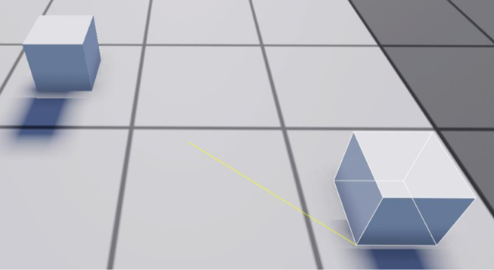
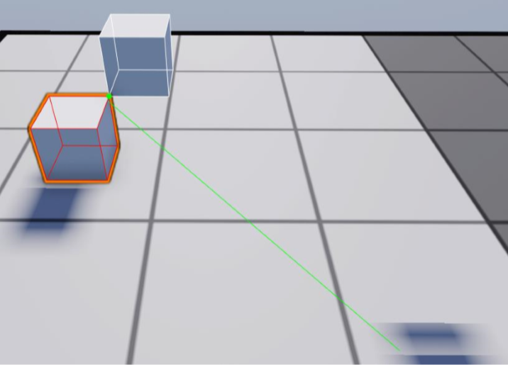
If user releases the left mouse button when the line’s color is green, the snap will be successful. If user releases the left mouse button when the line’s color is yellow, there won’t be any snap and entity will be translated to its initial frame.
Axis Constraints
When snap tool is active, you will see a gizmo on top of the nearest vertex. You can use axes of this gizmo to constraint axial movement or drag from middle to snap freely.